Saturday 26 February 2011

A few adjustments are necessary

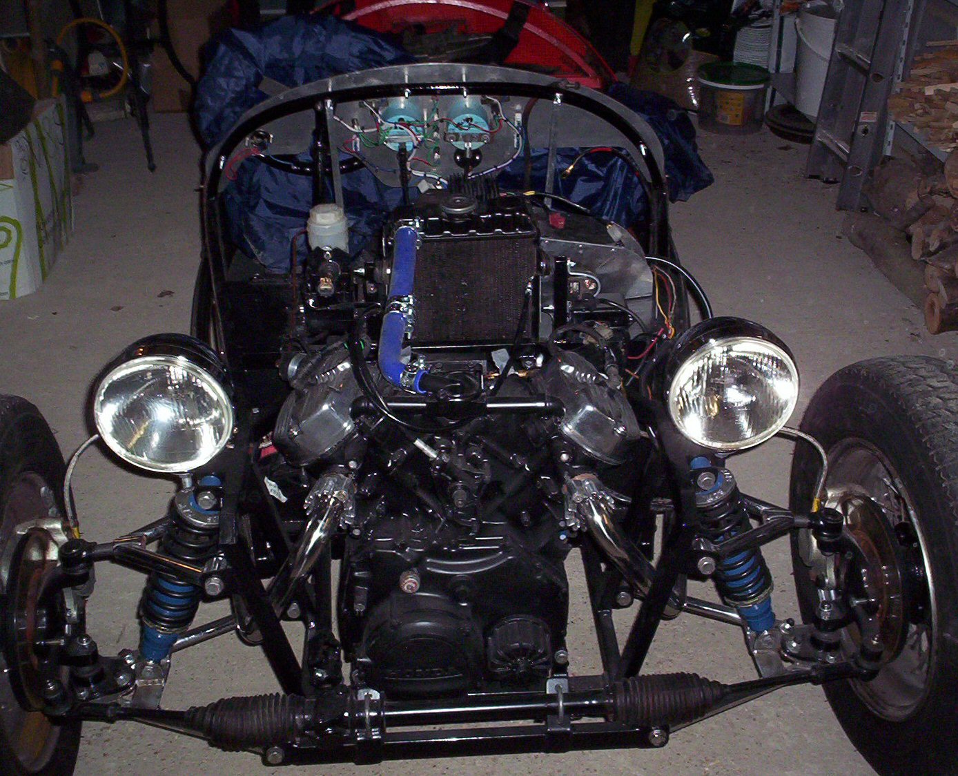
Wiring can get a bit messy!


Having followed my instincts with the location of various items I thought it about time I retrieved the bonnet from its lofty perch in the roof of the garage and made sure it fitted OK. Whilst I had expected to trim some of the aluminium from the radiator vent duct, I was surprised to see that the CDI unit slightly fouled the bonnet, as did the coils. The latter was a simple matter as I just had to swivel the brackets through 90 degrees, but the CDI unit could obviously not stay where it was, even though it only fouled by half an inch or so, so I repositioned it on the side of the radiator ducting. Another casualty was the starter solenoid, which again, barely fouled the bonnet where it was attached to the radiator support post, but sufficiently enough to force me choose another position. The solenoid has ended up where the CDI unit was, although tucked right up to the radiator.
~
With the bonnet now back in play I removed the old windscreen which has a rather curious profile - the driver's side had been cut down to about 5" high, whilst the passenger's side is about 7" high. I believe this was done so that the driver could see over the screen rather than part through the screen and part over. Nevertheless, I had decided that it was Brooklands Aero screens so set about researching a suitable source. In total I found about 10 suppliers and a variety of prices, but opted for a pair supplied by Vintage Car Parts at £116. Prices do seem to vary greatly, and some seemingly cheaper ones had not included the Value Added Tax (VAT) which pushed their price up considerably. I cannot understand why any supplier quotes net prices when we all have to pay the darn tax anyway.
~
I had spoken to the guy I will be using to respray the bonnet and rear panel to ask if I should fit (and then remove) the Brooklands screens before taking the body bits to him for painting. The resulting "yes" meant another job to remove the pegs for the tonneau cover, as well as the luggage rack from the rear body section. The various holes from the old windscreen, front fuel tank filler, and luggage rack will be filled prior to painting. I also need to enlarge the holes in the side of the bonnet to allow the hot air from my radiator duct to escape. At present I am undecided whether to have a rear facing scoop, or copy the original Morgan approach with large vent holes. I'm veering to the latter with a suitable mesh attached to the inside of the bonnet.
~
I've made the aluminium cover for the steering column but got a little distracted by the wiring as some more electrical bits arrived in the post so I have yet to finish the ali panels on the driver's side. I have spent some time connecting the battery cut out switch, and fixing terminals to the lighting wires. However, with limited time available this weekend I was very frustrated trying to wire up the light switch. I had noticed last year that the side lights went out when main beam was selected (position 3 on the lever switch) and had assumed that it was wired incorrectly, but when I finally put the multimeter on the switch is was evident that the switch was faulty as one terminal was completely dead. Back to the Internet then to order a new one.
~
Roger

Wednesday 16 February 2011

Ebay isn't always the cheapest option


The metalwork takes shape


Choke fixed to transmission tunnel


Unable to resolve the problem of fixing the very short CX500 choke cable in a suitable place, I resorted to Ebay which had literally hundreds of choke cables on offer. I quickly discovered that none of the motorbike ones were suitable - all were too short or had unique fixings. That left the car choke cables. I had estimated that the optimum length of inner cable was about 120cm so the hunt began. One feature of car choke cables was very evident - they didn't have a soldered nipple on the carburettor end. However, no sooner had I discovered this than I found a solderless nipple on Ebay, so bought that. Most of the advertisers didn't specify the cable length, but after hunting through nearly 200 listings I found that a cable for the 1971 left hand drive Triumph Spitfire was ideal as the supplier had kindly given its length. Mind you, the £13.95 plus postage price tag seemed rather high in comparison to other choke cables (and it wasn't a genuine Triumph NOS cable anyway). I therefore tried James Paddock - one of the leading suppliers of Triumph spares and was pleased to see that it was just £6.95 delivered so I've ordered one from them.

~

I visited my local steel stockholder on Tuesday and bought a 1 metre square sheet of 1mm aluminium so that I could fabricate the panels I needed between the bulkhead and dashboard. Although I have a metal guillotine, it did prove a little unwieldy to cut due to its size. I had also purchased a metal folder some years ago and this has proved to be invaluable for a variety of jobs. Its a very simple device that is clamped in a vice, but works very well. I was able to make a panel that covers the central portion from the dash to the bulkhead, and a smaller panel to the nearside where I have fixed the fuse box and flasher unit. One drawback with the folder is that folds with this device have to be in one plane only, so it requires a little imagination with vice, wood and other handy "bits" to make folds in the other direction.

~

I spent a couple of hours planning the electrical system refit - specifically the location of the CDI unit, regulator/rectifier - both of which need to connect to the leads from the alternator. One thing I have found useful (as a novice rewirer) is to print our several copies of the wiring diagram and then trace the key connections for each unit - e.g. CDI unit - and colour code the diagram with the correct colour of felt tip pen. I've found it so much easier to trace the start and the end of a particular wiring run by using this method - especially as my eyesight is not what it was given the size of the type on the wiring diagrams.

~

On checking the wiring diagram I noticed that the normally aspirated CX500 has a starter solenoid/relay with just two blade connectors whereas the turbo one I had fitted had four blade connectors. Not being sure what the extra two leads could be for, nor, in the absence of a wiring diagram for the turbo, which of the two were surplus to my current (sorry - wasn't intended as a pun!) needs, I decided that buying the correct one would be the best option. Naturally I turned to Ebay and found that exceedingly rough looking secondhand Honda ones were as expensive as new aftermarket ones, but that the aftermarket ones were 25% of the price of an OEM product from a Honda dealer. I opted for the aftermarket one on Ebay. This arrived within 2 days and was quickly swapped for the turbo one.

~

By the end of the week my attention turned back to the fabrication of the aluminium panels to cover the gap between the bulkhead and the dashboard on the passenger side of the car. As I wanted to house the fuse box and relays in this area, the resulting shape was quite convoluted. By Saturday evening I had finished the nearside to a satisfactory standard and started on the rather more awkward area over the steering column.

~

I spent a few minutes tidying up the lighting wiring and marking up the ends with their origins. I've also now connected up the leads from the alternator to the CDI unit, and the rectifier/regulator, as well as the coil connection too as the units are now fixed in their final places.

~

Roger


Sunday 13 February 2011

The cooling system gets me a bit overheated


Cooling system pipes now fitted


It sounds simple enough - connect the bottom radiator outlet to the water transfer pipe. In essence this is an elongated "S" shape of pipes, exiting the radiator to the offside of the car, turning through 180 degrees behind the engine, and then another 180 degree turn back to the water transfer pipe. The transfer pipe had been modified by Sam Day to include a small fixing plate to attach the pipe to one of the water pump bolts to ensure the pipe fitted squarely into the water pump aperture. Normally, this transfer pipe is located in two cradles on the near side of the engine case, but as I didn't want the cooling pipes running round in front of the engine, the pipework was being routed back behind the engine. It seemed a little ironic that having hunted for the transfer pipe for some time, that I was to cut most of it off and threw it away! (see picture)
~
My blue silicone coolant pipes were all a bit longer than required so they were cut as appeared to be necessary and fitted in place. Due to the reversal of direction (twice), I had to use stainless connectors to join each bend. The connection comprised - one 90 degree bend from the bottom of the radiator sufficient to take it through the bulkhead; another 90 degree bend to take it behind the engine, and then a 180 degree bend back to the cut down water transfer pipe. In all, there are six clamps and two stainless connectors. The first attempt pushed the pipe too near to the engine and so out it all came and a careful bit of trimming with a craft knife and another assembly - much better. The pipe from the radiator now sat parallel to the water transfer pipe so the 180 degree bend completed the run. Whilst the pipework is finished I'm still not sure how best to cover the remainder of the figure of eight shaped hole through the bulkhead (necessary for the rather convoluted turbo cooling system).
~
With the cooling pipework in place I could fit the carburettors which took no time at all. I did scratch my head a bit when it came to the throttle cable, but that was soon in place. Same with the clutch cable, but being unhappy with the normal loop over the top of the engine, I've routed it towards the nearside and then back to the clutch actuating arm.
~
What does have me puzzled is the choke cable. How anyone can fit the standard CX500 choke cable is beyond me as its far too short to be fitted within reasonable reach of the driver.Although I've bought a new CX500 cable, I'm very tempted to source a longer choke cable from a car and fit that instead.
~
With a busy social weekend I had little time to work on the JZR but have tidied up the fuel pipe run from the rear of the car forwards. The previous route took the rubber fuel pipe through the bulkhead where the gearchange lever runs. Feeling that this was a rather dangerous route I've cut a 25 mm hole high up on the vertical bulkhead on the passenger side and used a rubber grommet to protect the fuel pipe. I'm still not sure exactly where to locate the fuel pump which needs to be the next move.
~
Roger

Friday 4 February 2011

Lots of half finished jobs

Gradually looking more complete


The struts for the aluminium cover (to be made!)

The top and rear water coolant pipe


Another week of bits and pieces, and a number of half finished jobs, due mainly to not having all the parts I need.
~
The exhaust spacers arrived from John Ziemba, together with the long tachometer cable so I was able to quickly fit the latter, and jiggle around with the exhaust too as the pipe reducers had also arrived in the post. However, having thought that I had two suitable clamps for the silencers, I found I hadn't, so did a tour of the motorcycle outlets, motor factors, and in desperation, Halfords. The closest I came was one of the motorcycle outlets who had 47mm to 51mm stainless clamps, but not the 43 - 47mm size that I needed. Back home, and the Internet to the rescue where I quickly found suitable clamps at a much more acceptable price - £2.95 each rather than £7.95 each for the slightly larger ones at the retail outlet. I now just have to wait for the vagaries of the dear old Royal Mail to deliver same. Given that they are still delivering Christmas cards posted 10 days before Christmas, I'm not too optimistic of a quick delivery. Unfortunately I couldn't do any more on the exhaust until the clamps arrived as they had to be fitted before the reducers are pushed into place. Had a bit of a game with the reducers as, in theory, I needed all three reducers to plug the gap between the 38 mm down pipe and the 44 mm ID of the silencers. However, they just wouldn't all fit so I had to use two of the reducers and give the clamp a serious bit of tightening.
~
Having already found that none of my collection of clutch and throttle cables was suitable, Sam Day had acquired a throttle cable and choke cable for me. I collected these when I delivered my water transfer pipe to him on Monday so that it could be modified to suit the short return to the radiator. That just left the clutch cable which I ordered from David Silver on Tuesday. Still, I was able to finally fathom out how the throttle cable fitted as the thread at the pedal end was a tad bigger than the turbo cable and I needed to enlarge the hole in the pedal box to accept it. I really wasn't overly happy with the rather casual fit of the throttle cable to the throttle pedal so have used a small cable tie to ensure it doesn't jump out.
~
Sam had tested the two CDI units I bought on EBay and found that one was working and one wasn't - so much for the legend "In good working order"! Having got the working unit home I quickly drilled a couple of holes on the bulkhead in a position that would allow easy connection to the leads from the alternator. As the connectors on the leads from the alternator were looking a little corroded I mused on the best way to clean them, then hit on an idea - what about Coco Cola? I filled half a jam jar and dunked the three connectors into the Cola and watched 10 minutes of fizzing before becoming bored and having lunch. After lunch I removed the connectors, washed them in water and was amazed at the shiny appearance. That should give a good connection!
~
As an aside, the turbo engine and ancillaries were collected by the shippers during the week and will be on their way to Australia shortly.
~
Another package received this week was the coolant pipework, connectors and clamps. Fitting the top hose was quite straightforward as a 45 degree bend from the thermostat housing creates a direct line to the top radiator connection. A bit of pipe cutting and clamp fitting, and the top connection was quickly finished. The bottom hose connection was not so easy though as access is much more restricted. My plan was to use two 90 degree bends to take the coolant pipe through the bulkhead and then return behind the engine. This would then enable me to connect up to my water transfer pipe, which will be parallel to the hose from the radiator, by using a 180 degree bend. Easily said, but not quite so quick to achieve as the top hoses, primarily because access was difficult. Nevertheless, after some changes in the position of the clamps, and some judicious cutting of the bends, I now have a coolant pipe sitting patiently beside the water pump, awaiting the arrival of the transfer pipe so that the final connection can be made. On the turbo installation, the coolant overflow bottle was attached to the outside of the body - a feature that I felt was rather unattractive so I intend to fit a smaller round bottle that I will mount in the engine bay, probably on the nearside, and out of sight. Having checked around, it seems that the overflow bottle fitted to the small chassis Triumph range (Vitesse, GT6) will do the job nicely so I've ordered one of those. Oddly, the rather tatty looking secondhand ones on EBay are more expensive than new ones from the leading suppliers.
~
Due to the modifications being done to the water transfer pipe, I have not attempted to fit the carburettors yet, as they sit directly over the water pump and rear coolant pipe. However, once the transfer pipe has been fitted I will be able to fit the carbs, fuel pump and fuel supply pipe. I've also bought a fuel cut off valve that works if the car is bumped - just as a precaution.
~
With visitors this weekend I had little chance to do anything substantial but have managed to make two aluminium struts to support a cover for the area between the dash and the bulkhead, as well as a central strut from the bottom of the dash to the bulkhead to give the dash more support.
~
Roger